Many structural implementations are possible to dissipate the kinetic energy of the bird to protect the internal assemblies. From thickening layups in the vicinity of the leading edge to adding metal plates inside of the layups or implementing V shaped deflectors. The simplest solution was first tested which was implemented as a D shaped spar like the ones seen on helicopter blades. It was planned to test multiple D-Spar thicknesses and maybe other configurations but during tests it showed that the minimal D-Spar configuration with only 1 mm thickness was adequate on completely stopping the bird to penetrate the wing.
The bird was modelled using Smoothed Particle Hydrodynamics (SPH) which is a meshless numerical method appropriate for applications involving extreme deformations. It consists of discretizing the body with individual particles (PC3D elements in Abaqus, by default one element equals one particle). Method is based on pure Lagrangian modelling scheme for each particle. Relevant physical properties are calculated for each particle as an interpolation of the values of the nearest neighbouring particle(s) and then the particle responds according to these neighbouring states. Beyond engineering applications, SPH method has been proven useful in physics as well - gravity currents, wave propagations, free surface flows, etc.
Bird material was defined using Mie-Gruinesen Equation of State model which provides a hydrodynamic material model in which the materal's volumetric strength is determined by an equation of state. Specifically Us-Up Hugoniot form was used which constants c0 (speed of sound) and s define the linear relationship between the linear shock velocity Us>, and the particle velocity Up. One more property is needed and that is Gruneisens ratio, Γ0 . Bird material properties are found in the table below.
Bird EoS material properties
Mass of the reinforced wing is now 35.7 kg which equals to 3.2 kg added in the form of aluminium spar and 2 GFRP layers in the area where the spar touches leading edge CFRP, to prevent galvanic corrosion.
Structurally implemented reinforcement is shown in the image below.
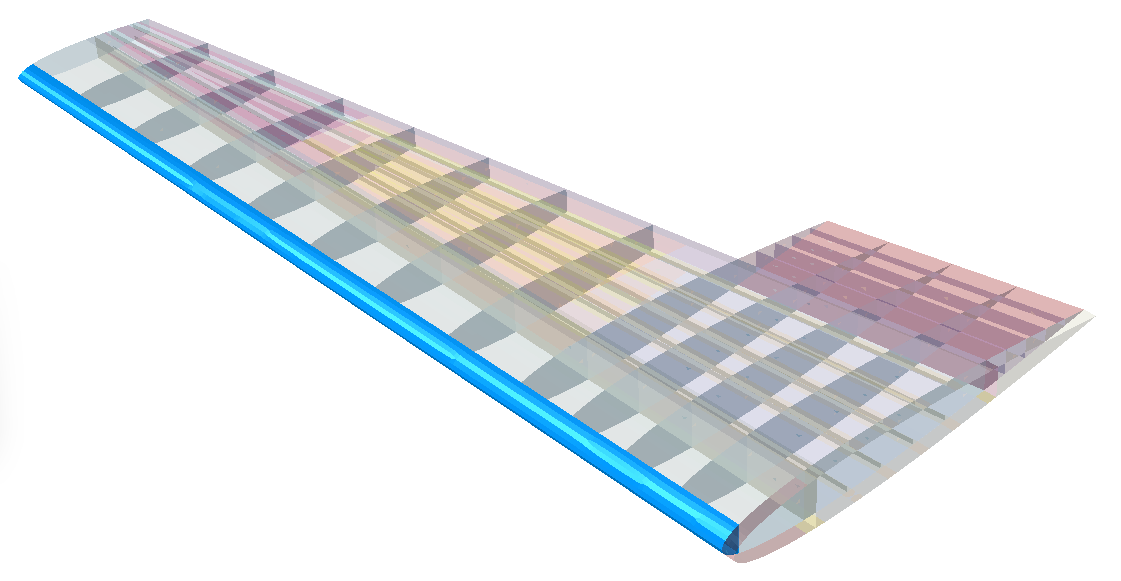
D spar reinforcement
Initial bird velocity represented relative velocity between the bird and the aircraft and it equaled to 115 m/s. Point of impact was chosen arbitrary.
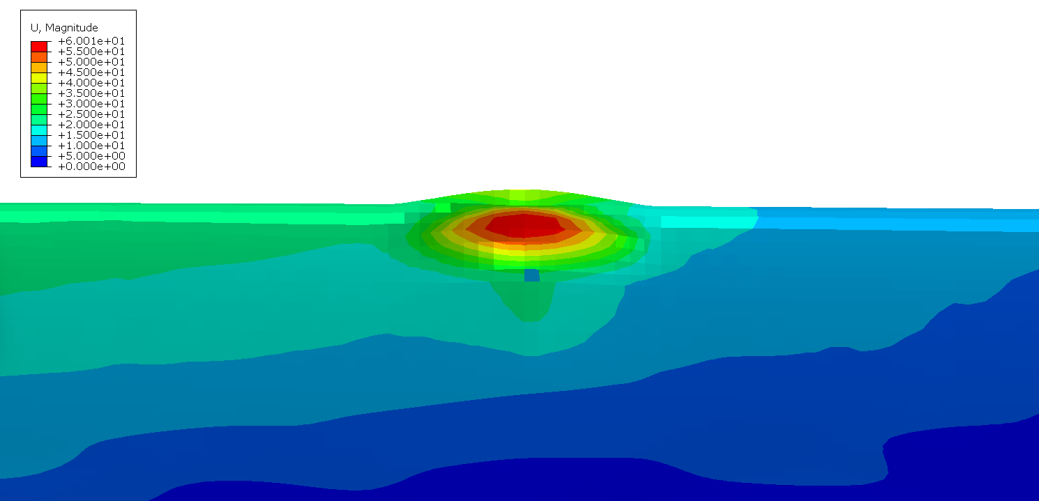
0 degree impact
45 degree impact
Permanent leading edge indentations are: 42.6mm for 0 degree case, andd 60mm for 45 degree case. Result images provided below.
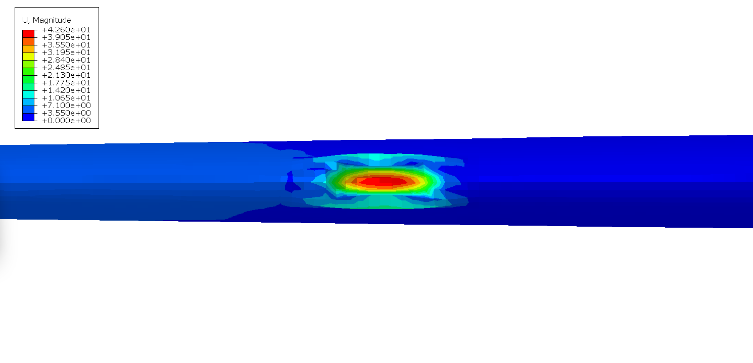
0 degree permanent deformation
45 degree permanent deformation
Maximum wing tip displacement for both of the cases peaks around 64 and 66 mm, where during the 45 degree impact wing shows bigger rebound and consequent oscillations.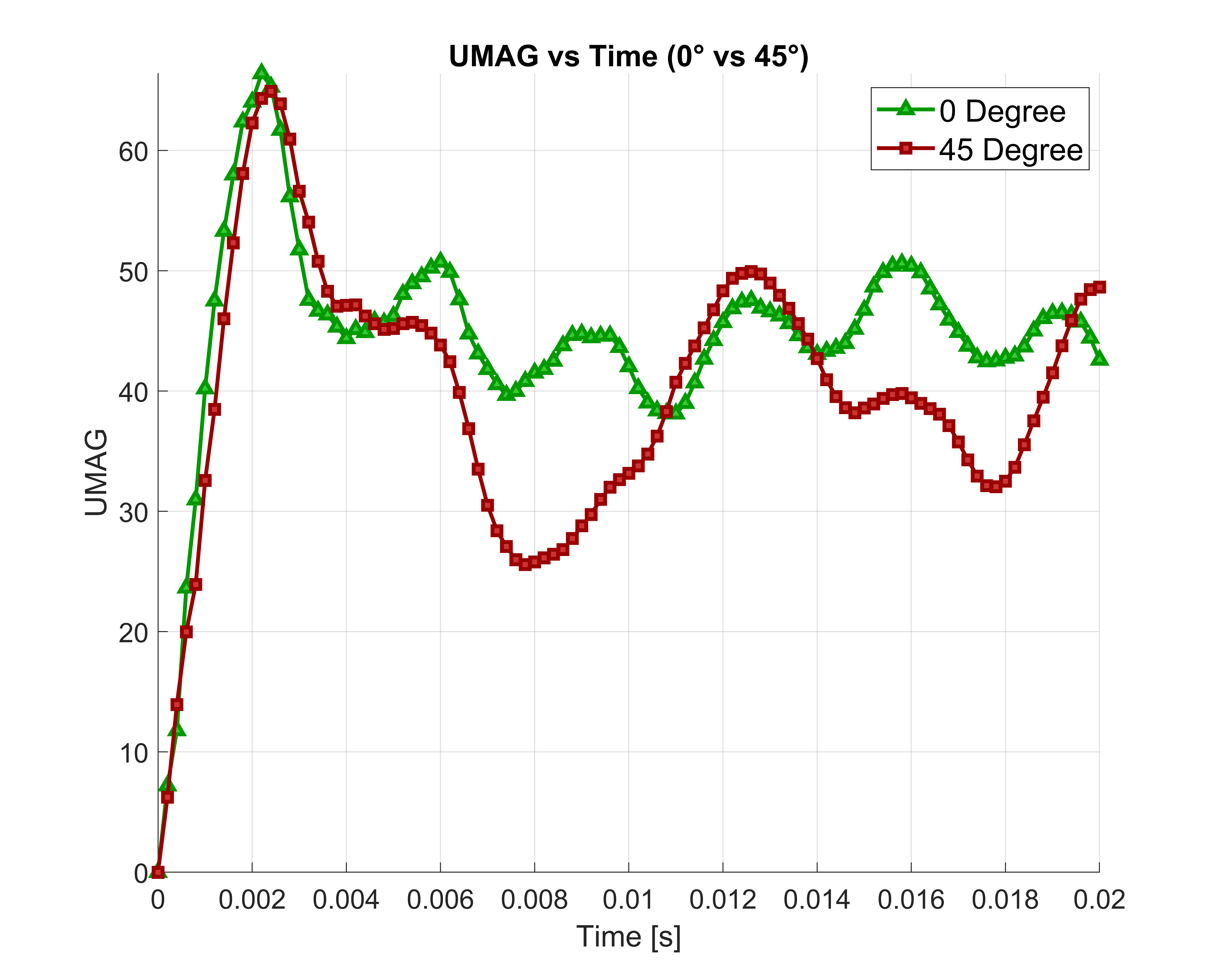
Wing tip displacement during bird impact
Composite layers at the location of impact were destroyed, but since not all plies were damaged, aluminium ply surviving the damage, no shell elements were deleted. Below are presented damage variables JCCRT (Johnson-Cook Criteria) for aluminium reinforcement and PEEQ for the Nomex honeycomb, which was modelled as isotropic compressible material.
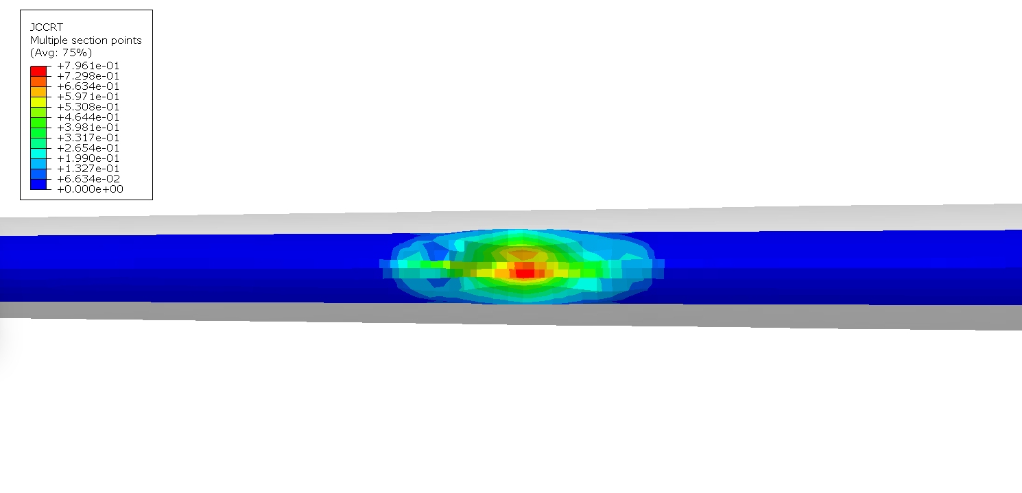
0 degree Johnson-Cook damage parameter
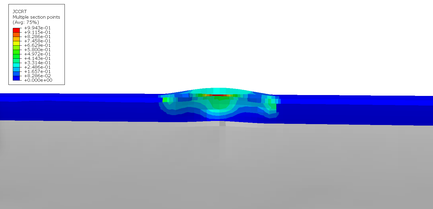
45 degree Johnson-Cook damage parameter
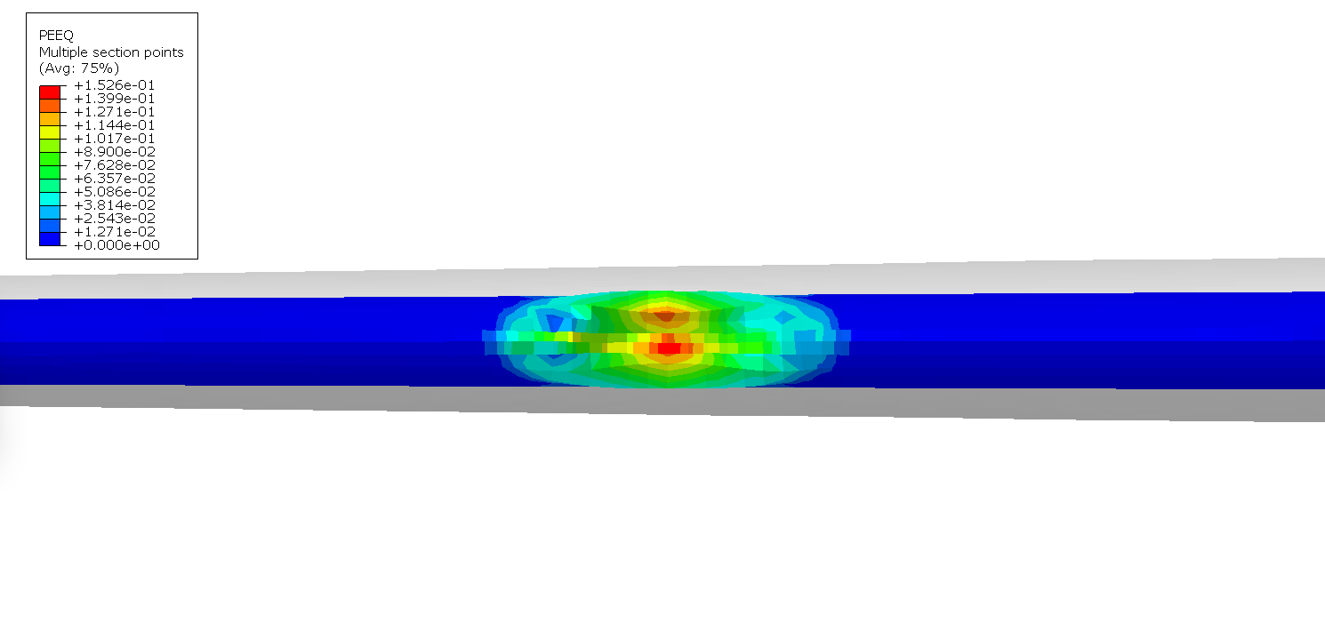
0 degree equivalent plastic strain
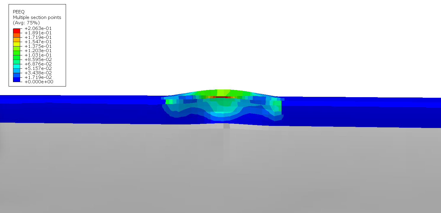
45 degree equivalent plastic strain
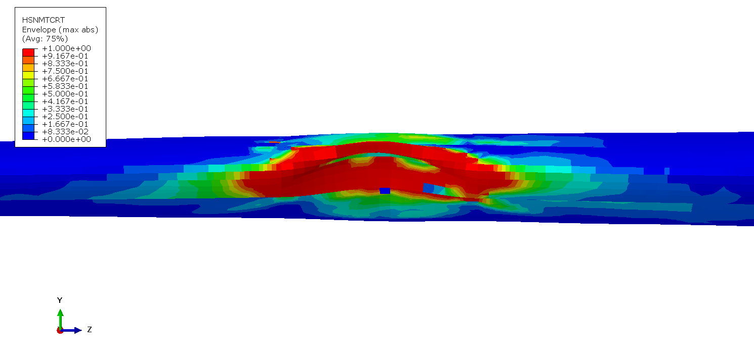
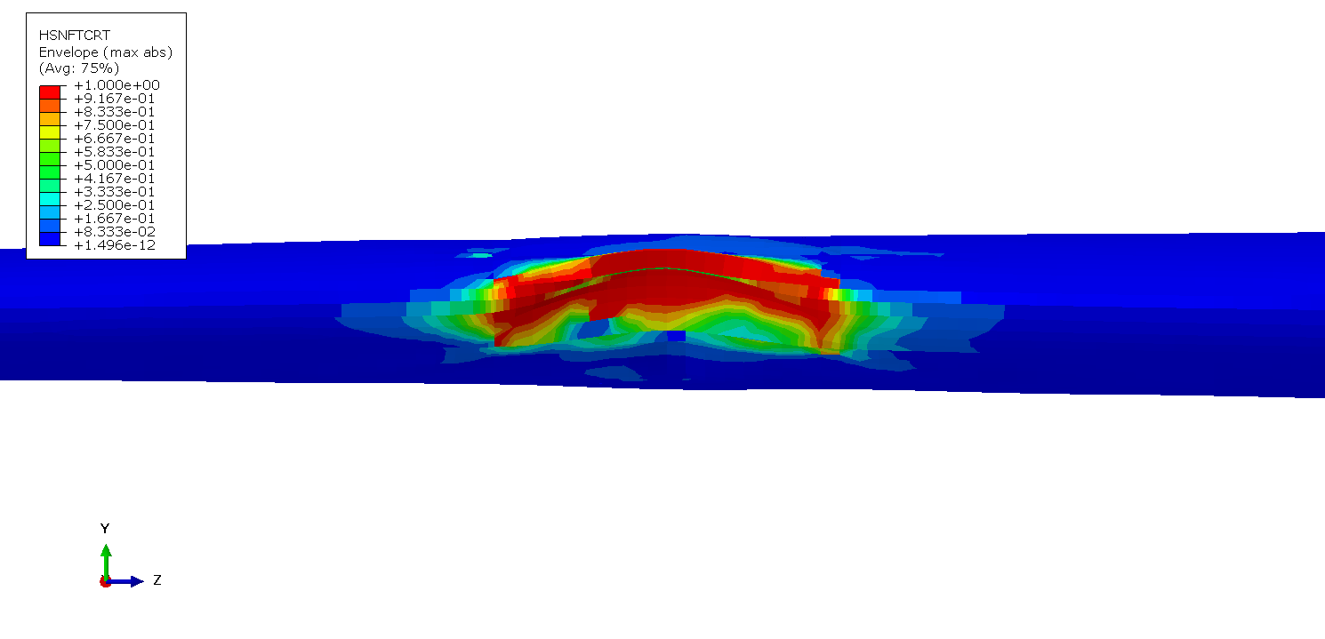
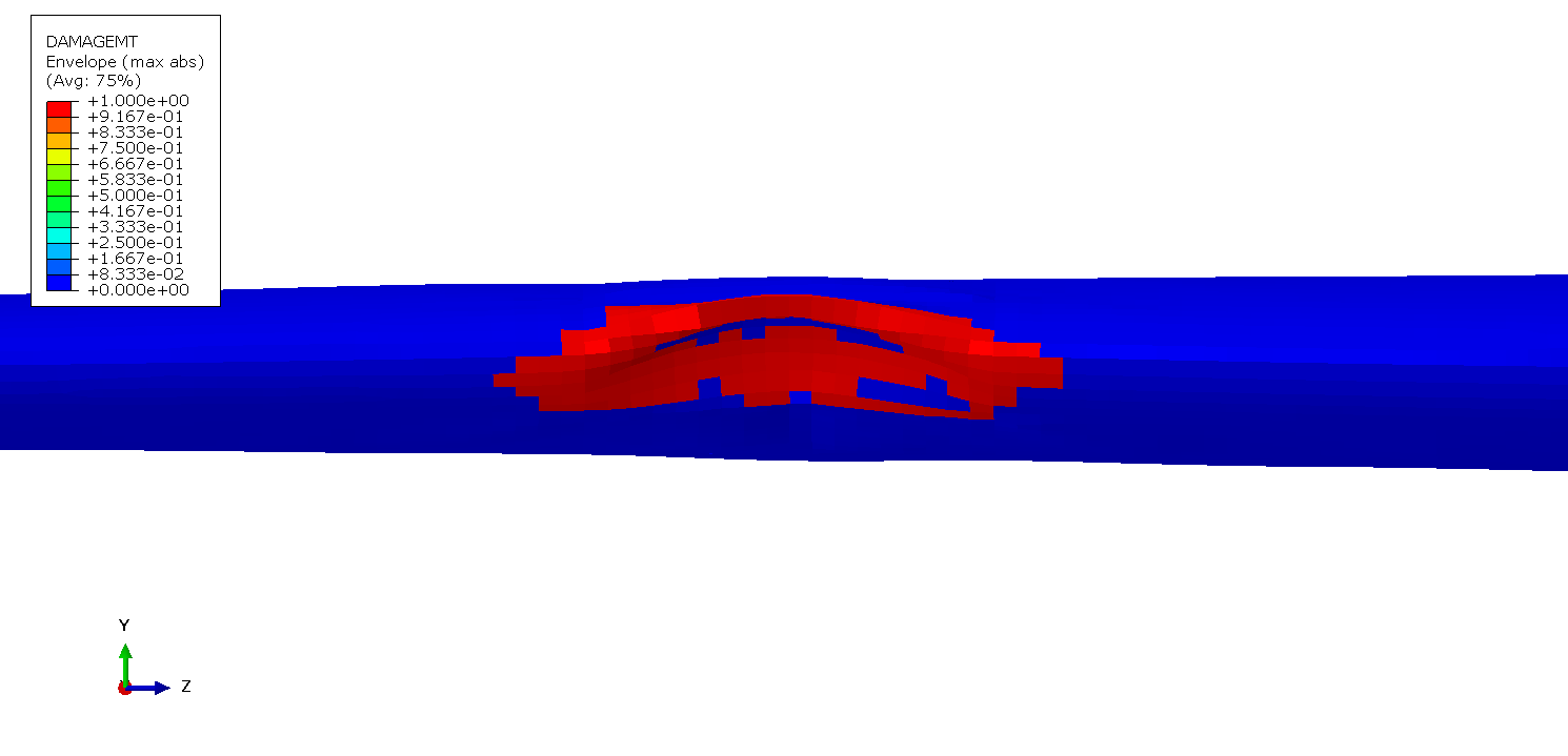
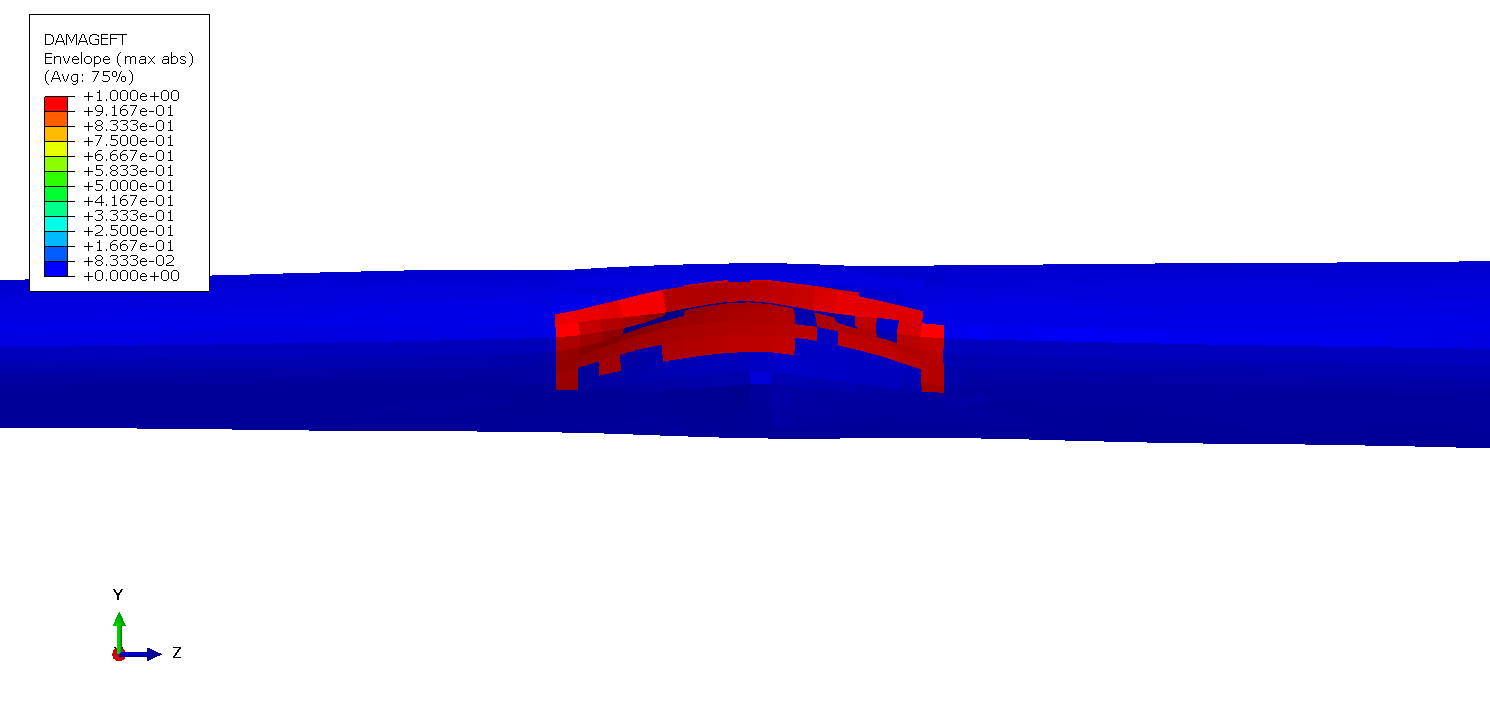
Hahin failure criteria indeces are shown in the images below. Both fiber and tensile indeces reached value of 1.0 with damage variable distribution corresponding to correlating failure index. Field variable distributions provided in the images below.
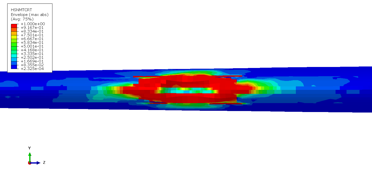
0 deg - Hashin Matrix Tensile Failure Index
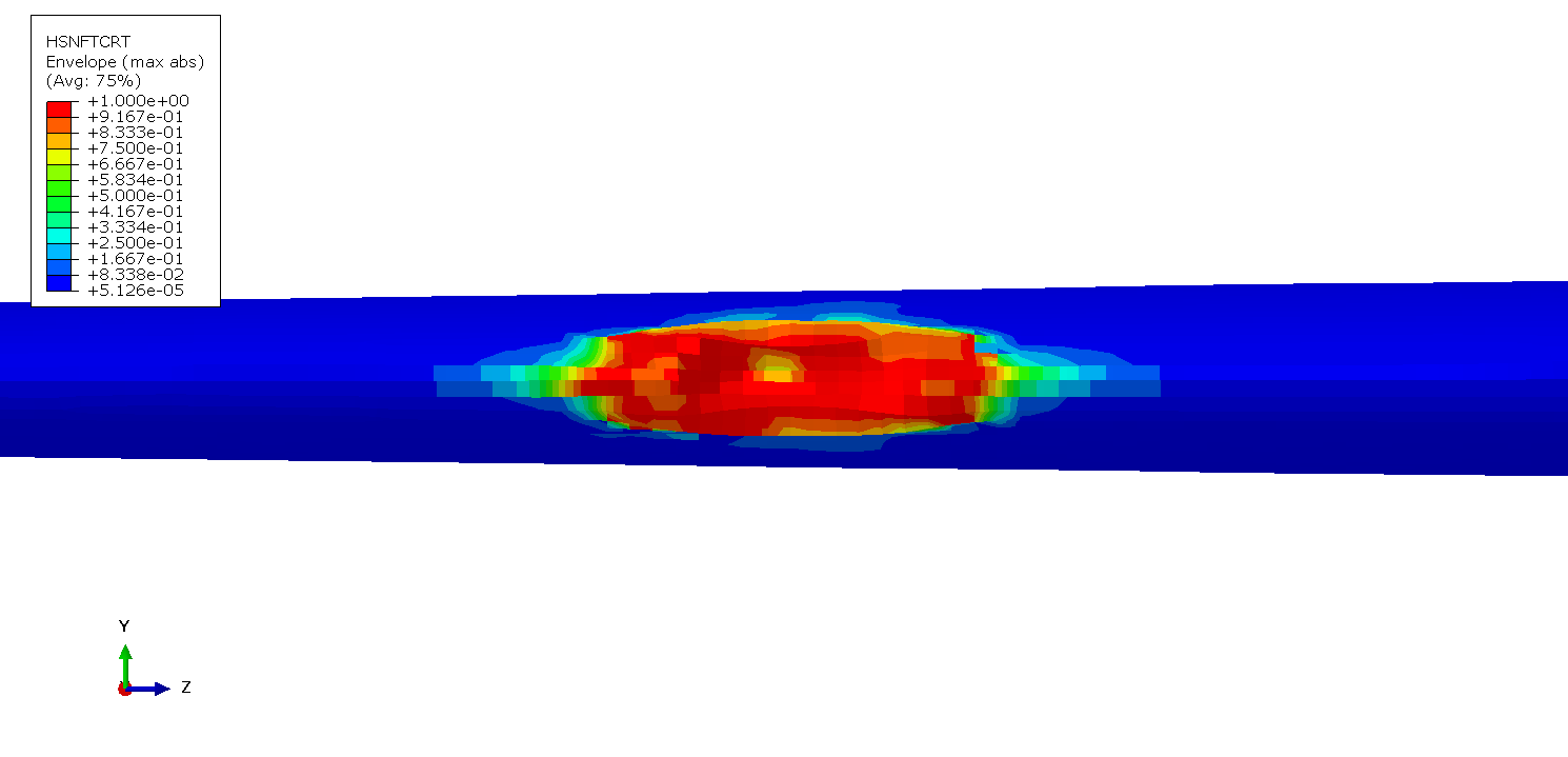
0 deg - Hashin Fiber Tensile Failure Index
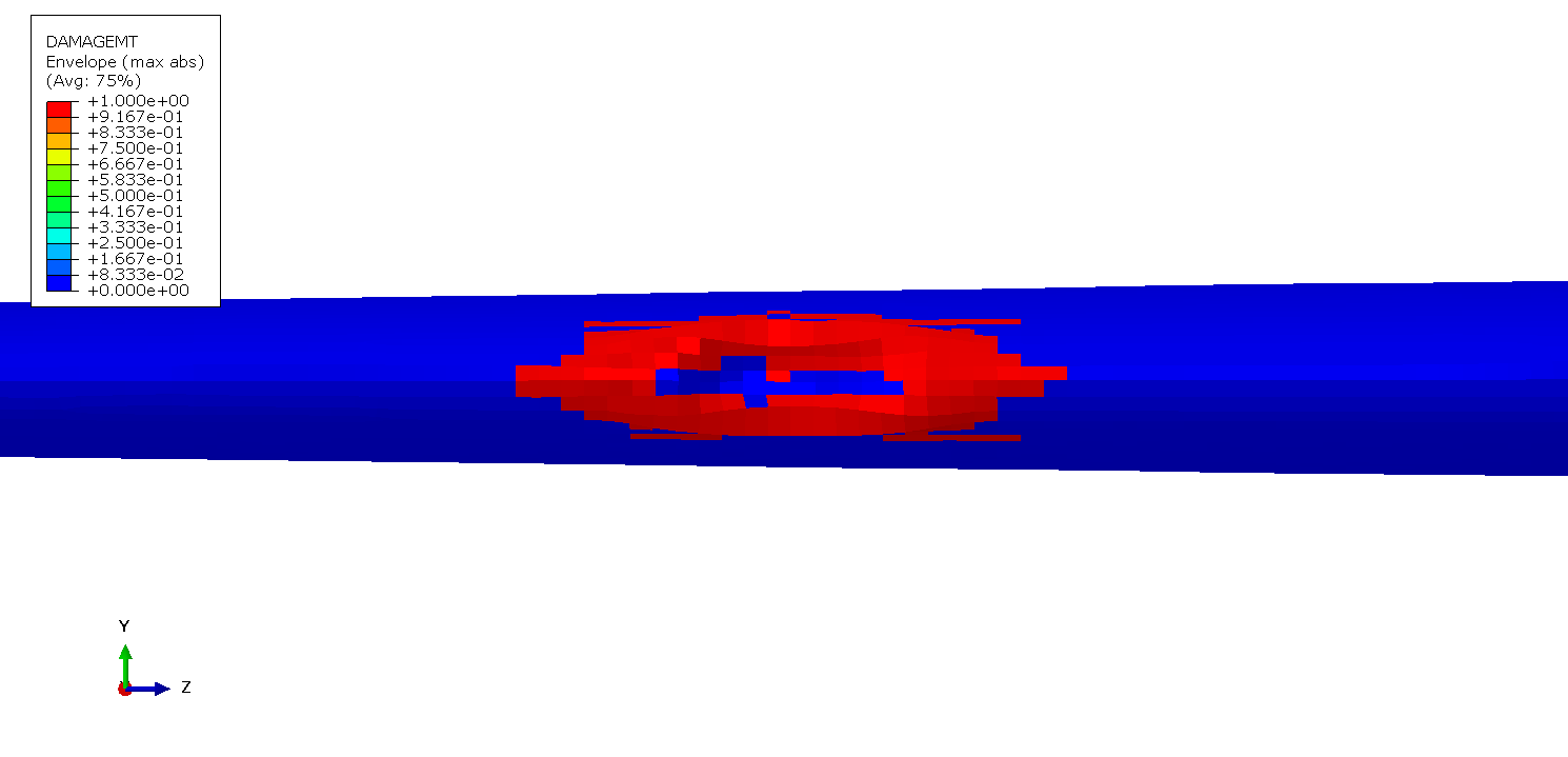
0 deg - Matrix Tensile Damage
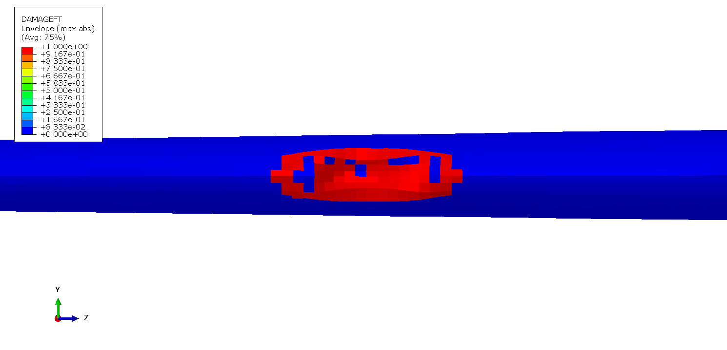
0 deg - Fiber Tensile Damage
45deg - Hashin Matrix Tensile Failure Index
45deg - Hashin Fiber Tensile Failure Index
45deg - Matrix Tensile Damage
45deg - Fiber Tensile Damage