Starting idea of the project was to test out how different stiffening solutions affect the structural response of the wing. After making few iterative models, it was noticed that only using the honeycomb core inside of the wings' skin, noticeably lowers the overall wing stiffness thus increasing the susceptibility of critical points to failure. It was then decided that the wing skin will only be stiffened using 'T' profiled stiffeners, or stringers, since combined use of honeycombs and stringers is redundant and adds unnecessary mass to the structure.
Spar Placement
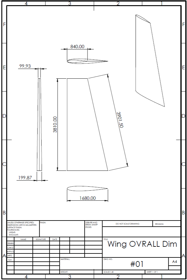
Usually, wing spars are placed at about 25% and 65% of wings' chord length. This matches the maximum thickness of the airfoil and the location of the aerodynamic center of the wing. By looking at the pressure field obtained in the previous chapter, it can be noticed that the maximum pressure acting upon the wing is located between 0 and 200 mm from the leading edge. If this was the only criteria it would lead to the front spar being positioned at 200 mm or around 12% of the root chord length so the environmental loads get effectively transferred to the spars caps. This positioning would put the front spar too much forward of the desireable wings center of gravity. Considering aswell, that the maximum thickness for the NACA0012 airfoil used for the wing is located at 30% of the airfoils chord, it was then decided that a good compromise between the two facts be to place the front wing spar at around 20% of the root chord or 345 mm from the leading edge.
Aft spar location was decided by measuring the control surface dimensions of the reference airplane Edge 540 (ailerons). Aft spar location on the root chord is measured at 1176 mm and 588 at the tip which makes it positioned at 70% of the root and tip chord length respectively. Aft spar will be used as a fixture location for the aileron.
Rib Spacing
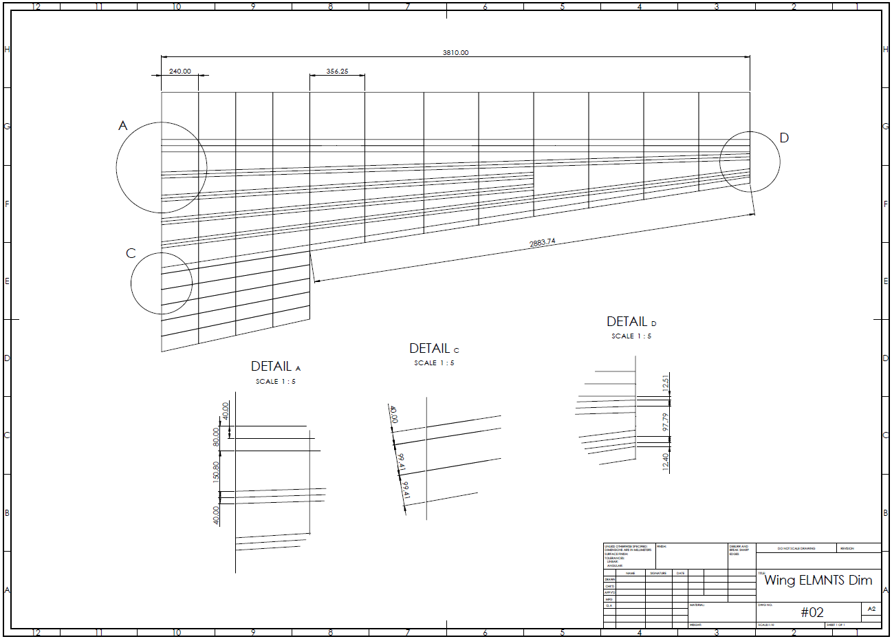
Rib positioning was obtained through an iterative process of simple buckle analyses and was set to 240 mm spacing (14.3% of the root chord length) at the inner section of the wing (pre aileron) and 356.25 mm spacing (21.2% of the root chord length) in the aileron zone. Since the wing is being optimized only in regards to the static analysis, buckle analyses might show the wing to be oversized (aswell as undersized) in regards to buckling - if that happens it is possible to increase/decrease the rib spacings and thus reduce the number of ribs in the wing. Considering the expected mass of one rib is around 200 g, (Mass of the inner section rib is 208 g) having 3 or 4 extra ribs throughout the wing doesn't impact the overall wing mass in any significant way.
Stringer Layout
4 stringers were placed equidistantly between the wing spars (measured from caps edges, wing box side). For the last 4 sections of the wing, only the outer stringers are present, since there isn't enough space for all of the stringers to be extended root-to-tip - low wing tip side buckling loads were considered during this design decision. To stiffen the trailing edge section of the wing, 4 top-to-bottom skin stiffening elements were also added with equal distance between all.
To avoid stress singularities present at the intersection of the three faces in non-manifold geommetries, a skin/cap overhang was added at the root of the wing. For this overhang area, no failure index values will be measured, and only the wing without the overhang addition will be considered during the optimization process.
Composite Design Guidelines
When it comes to deciding what layups will be used based on the chosen solution, certain composite design guidelines are to be followed. Important notice is that these guidelines were established based on empiric and experimental data and real world data is still needed to validate the design of a structure. Also, these guidlines were established back when fiber materials were still more brittle than what they are today, hence some OEMs circumvent these guidelines through rigorous testing, manufacturing methods and other design features that help in preventing delaminations and other defects. Design guidelines used in this project are as follows:
- Laminates are to be symmetric about their middle surfaces.
- Laminates are required to be balanced.
- Laminates will be fiber-dominated at least 10% of their plies in each of the 0, ±45 and 90 direction.
- Keep a reasonable number of primary load carrying plies away from the outer surfaces.
- Laminates should be symmetric and ballanced to minimize buckling strengths.
- Use of ±45 plies on the outer surfaces is recommended for stability critical laminates.
- Limit layer thicknesses withing laminate to 0.5 mm or less.
- The Poisson's ratio mismatch between a stiffener and apanel that are bonded or cocured together should be less than 0.1.
- The maximum percentage of plies in any direction will be 60% for composites where geometric discontinuities are present (holes, etc.)
- Laminates at mechanically-fastened joints should be fiber-dominated, contain no more than 60% plies at any single orientation, and contain no less than 35% ±45 plies.
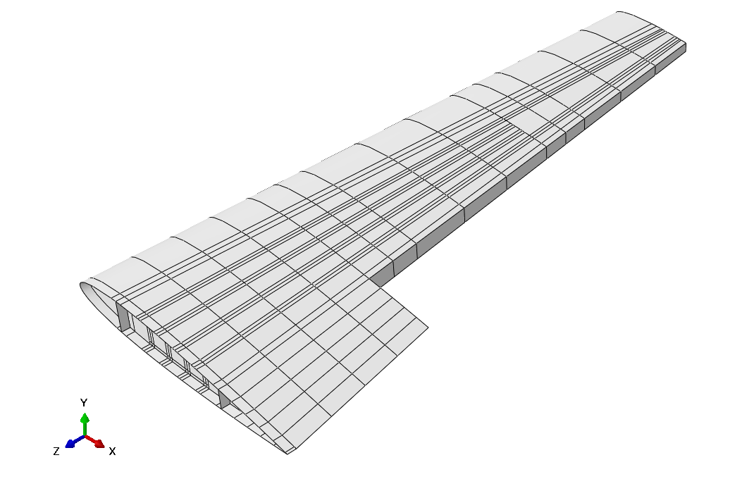
Wing CAD model imported into Abaqus CAE